AUTOMOTIVE CFD FOR DETERMINING AERODYNAMIC DESIGN COEFFICIENTS
A rather unorthodox concept car geometry was chosen for automotive CFD analysis and the force Coefficients were calculated.
Figure No.1: STL geometry
Turbulence properties were calculated from the wheel base length of the car and the Aerodynamic coefficients were calculated from the frontal area of the car. Here are the steps adhered to calculate the frontal area of the car using paraview.
Here is a brief video tutorial on how to calculate the projection Area or the frontal area of a car.
The projection area and the wheelbase length values are called inside the force-coefficient file, within the system folder.
Figure No.2: lRef(base length) & Aref(Projection Area)
The simulation was performed on a grid whose dimensionless wall-distance value was less than 1.0. A kOmegaSST turbulence model was adopted for a steady-state solver.
Figure No.3: Meshed STL geometry
Along with the car, the ground patch or the lowerWall is also considered as a 'wall' patch and there are 3 region refinements adopted. There is refinement immediately around the car, a refinement for the ground and a refinement for the wake region.
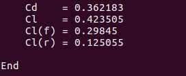
The simulation was run for 1500 iterations before the solver converged to a steady value of force-coefficients.
Figure No.4: Force-Coefficients
The residuals of the flow variables also satisfied the convergence criteria.
Figure No.5: Residual Plot
The pressure contour below indicates the stagnation pressure and the overall pressure distribution.
Figure No.6: Residual Contour
The flow streamline around the car geometry was also captured and illustrated below.
Figure No.7: Streamlines
The other plots are illustrated below.
Figure No.8: The k-plot & nut-plot
A good mesh is crucial to predict the right force-coefficient values.


Comments
Post a Comment